Page 8 of 10
Re: M20B20 to MegaSquirt build
Posted: Sun Jun 12, 2016 5:55 pm
by Jeroen
It is funny how the results appear to be on the low side, but throughout the cylinders. Did you perform the test at wide open throttle?
Re: M20B20 to MegaSquirt build
Posted: Sun Jun 12, 2016 7:29 pm
by BertjeConti
Jeroen, i performed tests with and without wide open throttle on the same cylinder, didn't make any difference.
While testing only the tested cylinder sucks air from the inlet, plenum is big and idle valve is fully opened, so there won't be much restriction with throttle closed.
In my opinion the results aren't funny at all, or the comprwssion tester is crap.
Maybe the air volume in the testers hose plays part in it.
Re: M20B20 to MegaSquirt build
Posted: Sun Jun 12, 2016 7:31 pm
by Jeroen
May be good to perform another test with another tester then!
Re: M20B20 to MegaSquirt build
Posted: Sun Jun 12, 2016 7:37 pm
by BertjeConti
Yup i think so too, but the difference betwen dry and wet test is what worries me most, that differece would another tester mostlikely show also.
Re: M20B20 to MegaSquirt build
Posted: Sun Jun 12, 2016 7:47 pm
by Jeroen
Agree, but I have no data on how these measurements compare witr other cars, anyone else?
Re: M20B20 to MegaSquirt build
Posted: Sun Jun 12, 2016 11:02 pm
by BertjeConti
I think i have to do the compression test again, because i used the measure set wrong

The set came without user manual (of course), and the thing that kept my mind was the air volume inside the hose and piping to the gauge, this air volume adds up to the compression chamber volume of the engine because the valve which holds the pressure in the gauge is situated in the gauge fitting itself.
So while doing a compression test by cranking the engine each compression cycle the compression camber of the engine and the hose and fittings of the measure set have to be pressurized again. so the air volume in the hose and fittings have to be added to the volume of the compression camber of the engine self.
So with a larger compression chamber (measure set hooked up) you'll get lower pressure readout as it should be.
i had already noticed that there was inside thread in the bottom fitting of the hose which screws in the spark plug hole, and tonight i found out why.

When using the hose assembly which screws into the spark plug hole it is possible to relocate the air valve from the gauge ssembly to the bottom of the hose assembly.
By doing so the air volume behind the valve does not add up to the compression chamber volume of the engine anymore, so there wont be any extra air volume anymore, which will result in more accurate measurement.

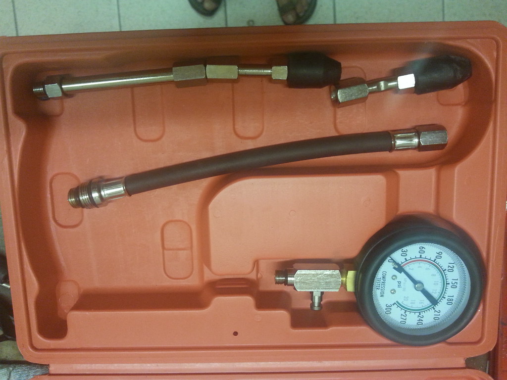
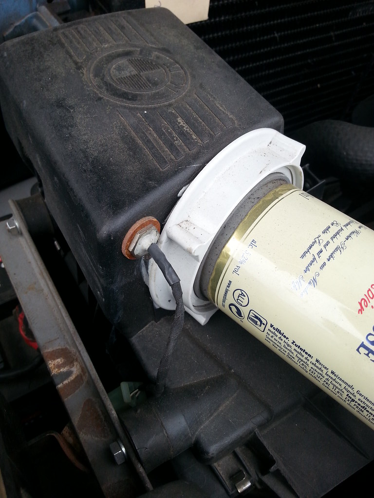
this is my compression test set:
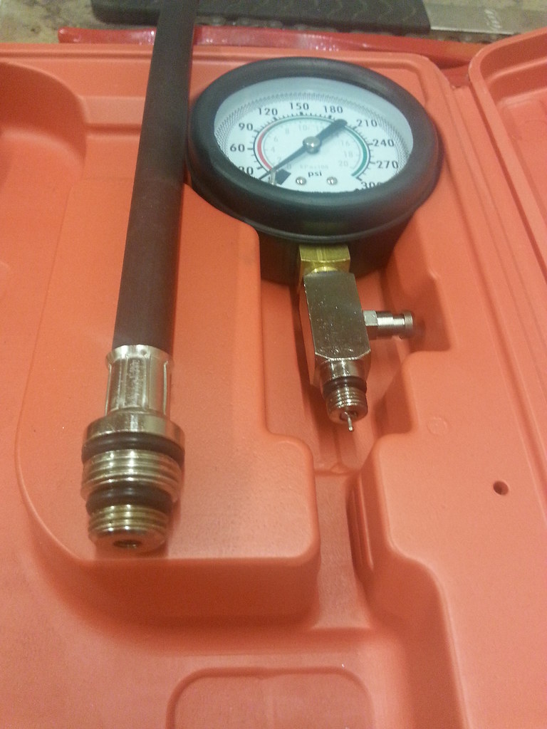
By delivery the air valve is in bottom of gauge assembly:
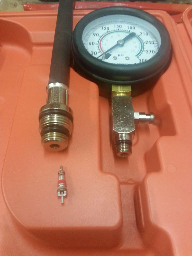
unscrewed the air valve:
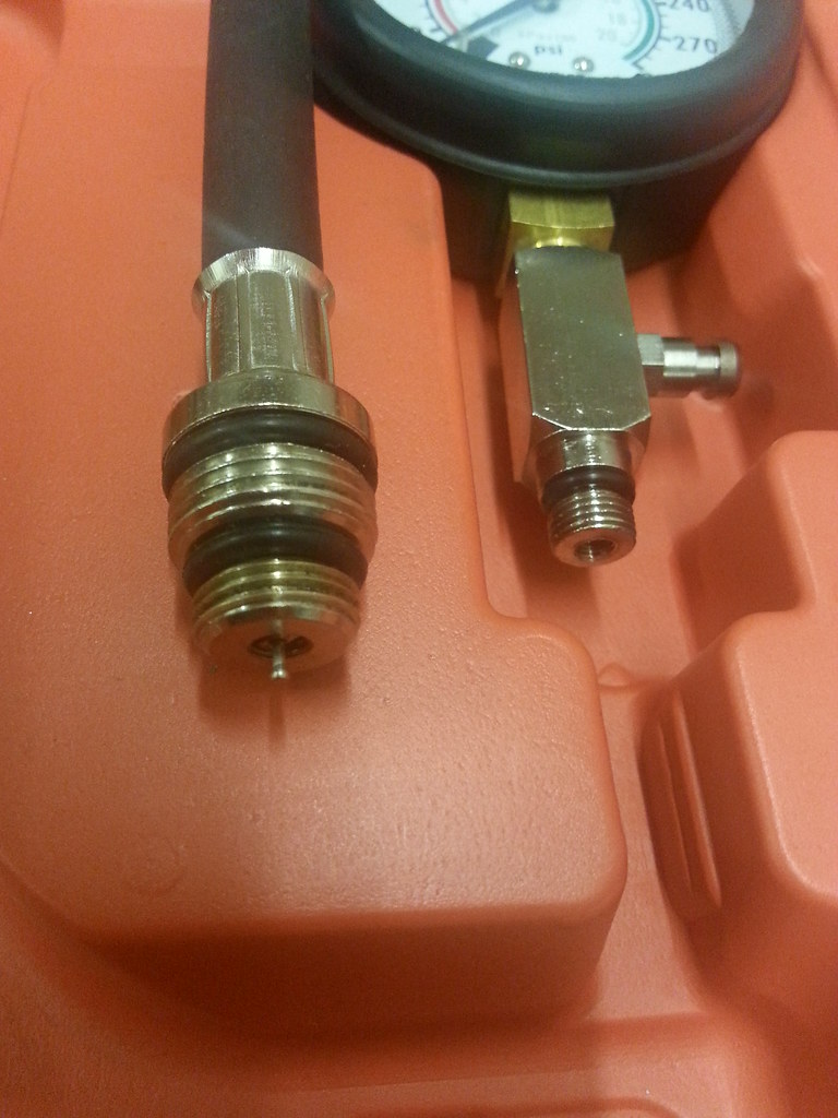
Air valve is now in the bottom of the hose assembly which screws into the spark plug hole:
I'll perform a new compression test measure session and post the results here.
Re: M20B20 to MegaSquirt build
Posted: Tue Jun 14, 2016 9:20 pm
by BertjeConti
Compression test revisited
So i performed a compression test again today, now with the air valve in the tool in the right place.
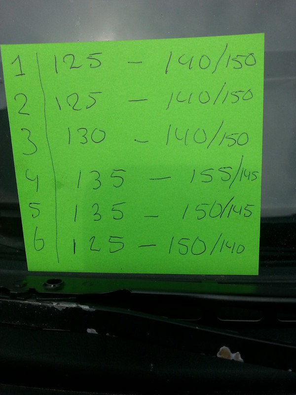
Differences with the previous measuerements are huge, around 25psi per cylinder
measurements performed today:
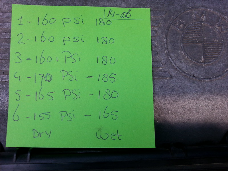
These today values make more sense
lowest value = 155psi, highest = 170psi, difference = 15psi which is about 10% and acceptable
in the wet test we see only cylinder 6 with a significant lower figure, which could direct to a slightly leaking valve, all other cylinders are wet around 180-185psi
difference between dry and wet test is around 15-20psi for cyl 1-5, which is also acceptable for an engine with 200k km
to compare here are previous (wrong) measurements:
i'm happy with these results.
Re: M20B20 to MegaSquirt build
Posted: Wed Jun 15, 2016 8:21 am
by steed
nice result there, I would expect 6 to shown the signs of the extra age given its the last bore to get cooling and its by the firewall with the most heat soak issues.
also I like the ide of an ecu spare, contingency!
Re: M20B20 to MegaSquirt build
Posted: Wed Jun 15, 2016 8:40 am
by Jeroen
This makes more sense, nice! Leave things for now!
Re: M20B20 to MegaSquirt build
Posted: Thu Jul 07, 2016 10:44 pm
by BertjeConti
fast responce Intake Air Temp sensor
A few threads earlier i've stated that the intake air temp sensor which is now in reacts a little slow. When the ECU calculates fuel with hotter intake air than the real air temp is, this causes a lean mixture. wirh normal driving this isn't realy an issue because the engine is running "closed loop" and the mixture will be corrected automaticly, thanks to the oxygen sensor in the exhaust.
But when full throttle is applied, closed loop control is left and fuel amount is purely on calculations. With the correct air temp reading this isn't a problem, but when the engine bay is hot (due slow traffic for example) the air temp reading is much higher as the actual air temp, which causes a lean mixture at full throttle.
Thats why i've sourced a fast reacting temp sensor which needs placement in the intake air stream. The old Air Temp Sensor is placed in the top of the air filter box, which seemed a not so good location afterwards.
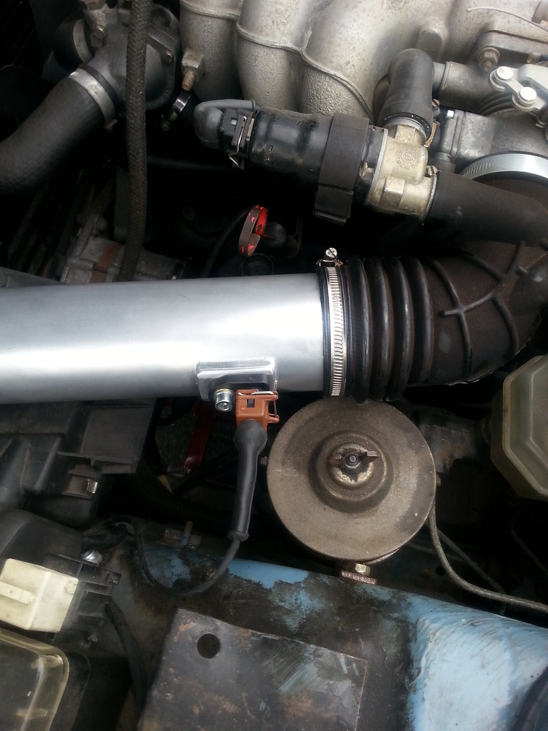
For the new sensor i've fabricated a new air intake tube between the Throttle body boot and air filter box. In this tube a bung is made which houses the sensor.
Placed the sensor today, readouds seems okay.
Here a pic from the old sensor location in the air filter box:
And here you see the new sensor in the new tube:
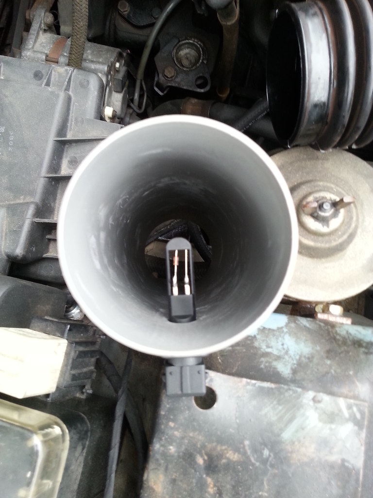
New tubing fitted with sensor in place in its bung:
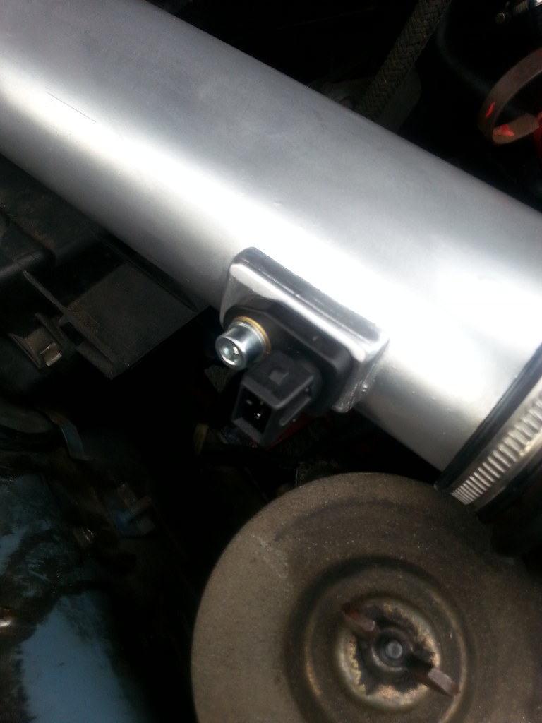
New air temp sensor connected to the wiring loom:
So another little improvement done.
Re: M20B20 to MegaSquirt build
Posted: Tue Jul 12, 2016 8:36 am
by steed
very nice! did the pipework come with the kit of did you make it yourself? I'd be interested to know what model/make the fast reacting sensor is from so I could possibly get one in the future...
Re: M20B20 to MegaSquirt build
Posted: Tue Jul 12, 2016 12:16 pm
by BertjeConti
steed wrote:very nice! did the pipework come with the kit of did you make it yourself? I'd be interested to know what model/make the fast reacting sensor is from so I could possibly get one in the future...
Hello Steed,
Yes i did the pipework myself it is made out of PVC, although it looks like aluminium.
The fast reacting sensor is china made copy from a general used Bosch IAT sensor, purchased at
(click here) ebay
i've tested the sensor in a range from -20 to 50 degrees and it's values are very close to a genuine Bosch IAT sensor.
The compatible Bosch sensor is listed in TunerStudio as "BMW325i air intake sensor", which makes tuning the ECU for this sensor a piece of cake.
Re: M20B20 to MegaSquirt build
Posted: Fri Jul 15, 2016 5:39 pm
by BertjeConti
Wideband controller and sensor is on its way
I've ordered the full LDPerformance wideband kit in the U.K.
Re: M20B20 to MegaSquirt build
Posted: Thu Jul 21, 2016 9:25 pm
by BertjeConti
BertjeConti wrote:Wideband controller and sensor is on its way
I've ordered the full LDPerformance wideband kit in the U.K.
arived today:
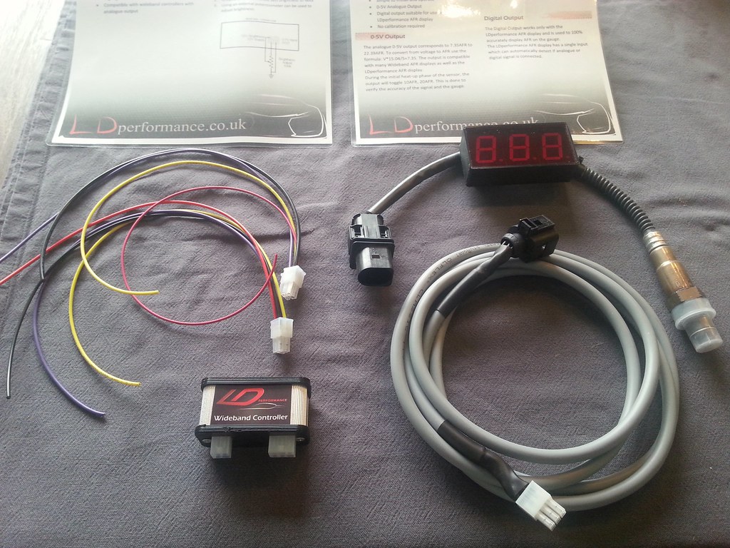
display is really big, but thats going hidden into the glove compartment.
some parst look like they are made with a 3d printer, not so stirdy.
the kit comes with the Bosch LSU 4.9 sensor which is the standard nowadays
Re: M20B20 to MegaSquirt build
Posted: Thu Jul 28, 2016 10:57 pm
by BertjeConti
Wideband AFR tuning
The wideband controller is in since last weekend and running OK.
I've started with a AFR table totaly filled with 14.7 AFR, so there wouldn't be any difference as running before with the narrow band.
In the area''s where i.m running "closed loop" the actual AFR is near 14.7 all the time. at idle and WOT (Wide Open Throttle) i'm leaving closed loop because the engine needs slightly richer as stoich when idling and rich at WOT.
At WOT the AFR wasn't as rich as i hoped it would be, it was still around 14 - 14.5 or so, which is a little lean for WOT. Maximum power is available around 12.5 AFR at WOT. so there should be some power gaining in that area with proper tuning.
A really nice feature in the Megasquirt is following, when changing the AFR in a certain area in the table, the actual required fuel is automatically recalculated , so when the VE tables are dialed in properly, and afterwards changing the desired AFR in a certain area the VE tables are still OK.
I already tried out leaning the AFR in the cruising area to 16 AFR, the engine seems happy with these numbers, only a vibration (hunt-stall) appears when throttle is released fully (overrun), so that needs some attention.
On the other side, at WOT the AFR wasn't rich enough as mentioned earlier, but changing the AFR in the table in WOT areas from 14.7 to 12.5 fixed that also.
i'm really happy with this big improvement.
