
This is a informative topic, with lots of technical info to come.
I know, this is the E21 forum, and this is about a E12 520-6, but, since there are no european E12 forums and my E12 is technical very very very similar to the E21 320-6, I think this story is appreciated here.
First, what is this all about: conversion to Megasquirt, lost of guys did it before, but my aproach is a little different, as are my goals.
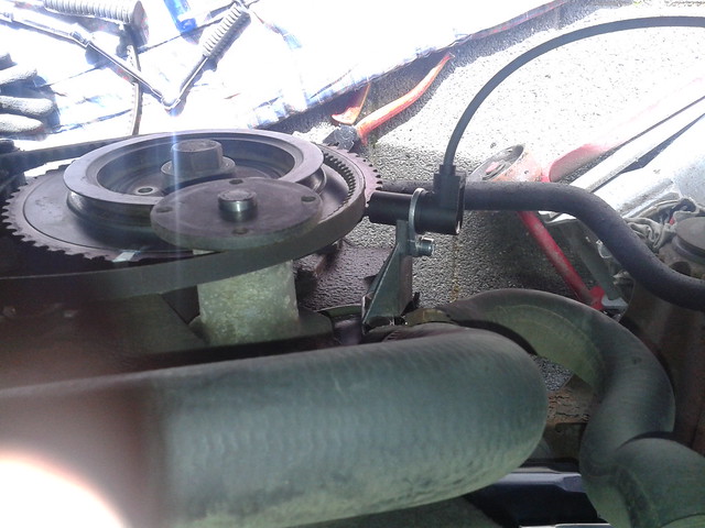
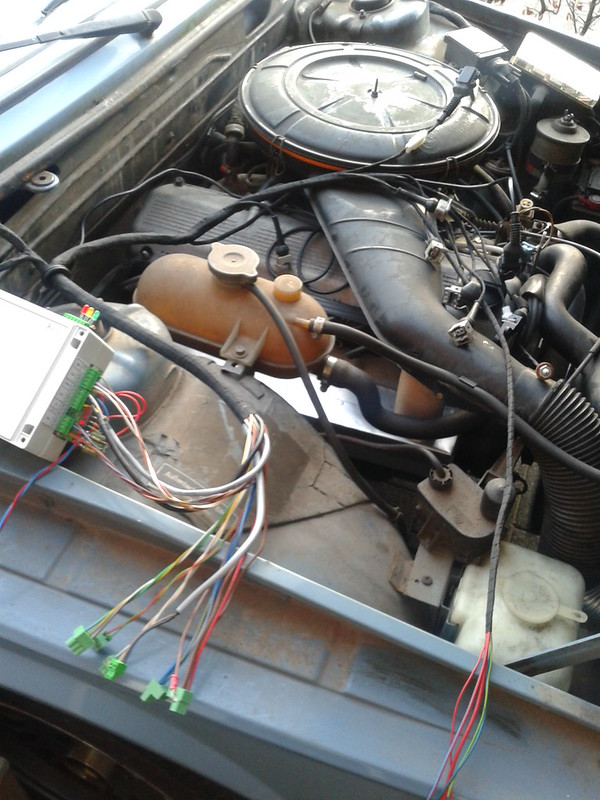
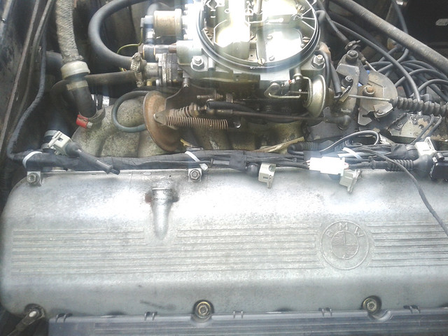
At the moment the car runs on it's stock carburettor and ignition and performs not bad at all. Fuel consumption however is massive. And once in a while it starves on idling during warmup, a problem which i can't tackle. The engine is stock and never overhauled, only the head is 10 years ago replaced for a 1981 head. The stock head was cracked near cyl-5, a common problem for the early heads due a casting fault. Engine has roughly 110k miles on it, oil consumpion is almost zero.
Why conversion to megasquirt?
1) because it is possible
2) i learn a lot about engines
3) i want to be able to tune the engine, so it runs a little bit cheaper
4) it is fun to do (my background is electronics)
What are my goals:
1) less fuel consumption
2) get rid of the stock carburettor and ignition, which are factory tuned for maximum safety
3) a little bit more power would be nice
4) sequential injection
5) wasted spark ignition
6) as cheap as possible
7) clean and relyable build
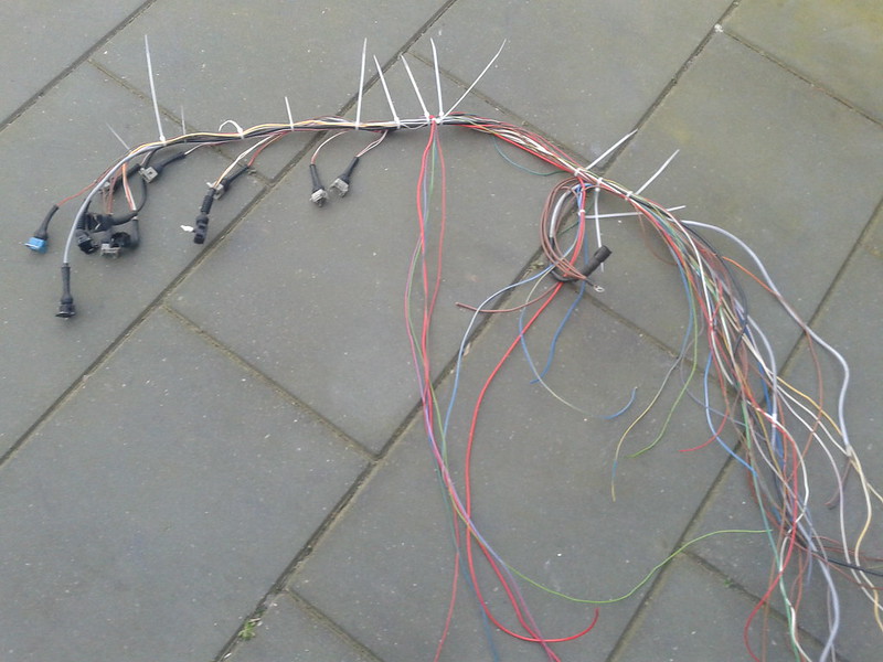
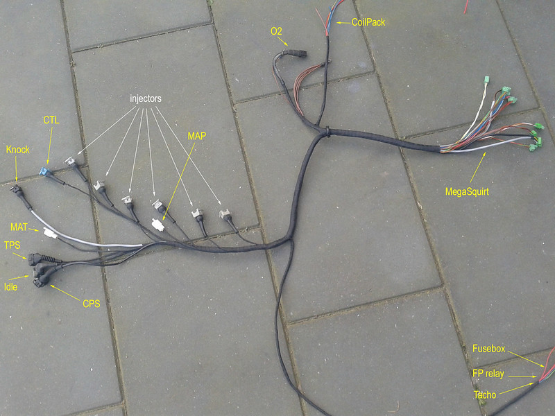
The last months i did a lot of internet study about the megasquirts and read a lot about other convertions or builds. At the same time I started to gather parts needed for my conversion. At this moment almost all the needed parts are present, and the build is progressing well.
The conversion will be a step to step conversion, because the car is a dayly user.
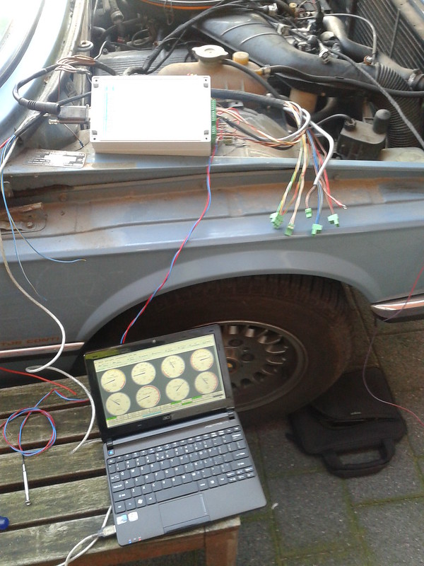
First about the Megasquirt:
I could have bought a MS2 or MS3 kit, but because i want some modifications done to the stock MegaSquirt it would be a messy build. The basis is the MS2 V3 megasquirt, but i've designed my own PCB with all the needed changes on it.
My MS2 based PCB features:
- 3 injector drivers with flyback for high-Z injectors
- 3 coil drivers
- knock detection
- 3 wire idle valve driver
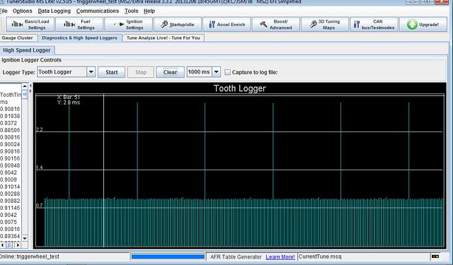
This involved a lot of testing on breadboard and so before the final PCB design was ready for manufactoring.
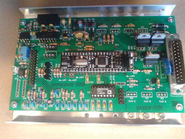
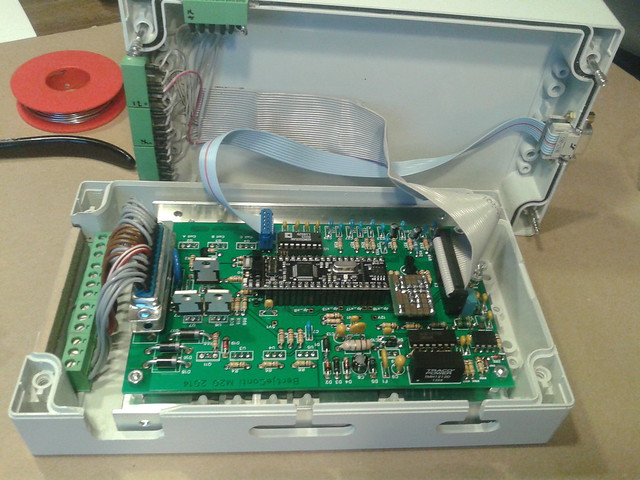
This is my MS2 based designed PCB with all the needed parts and cirquits on it:
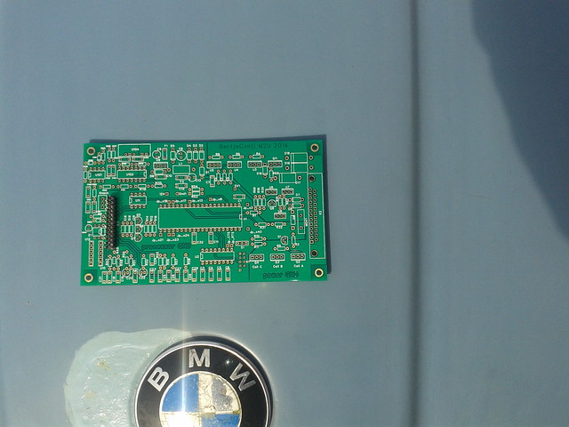
It is manufactured in china for me (china is a good supplier for cheap parts)
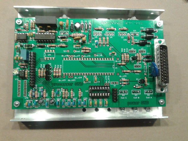
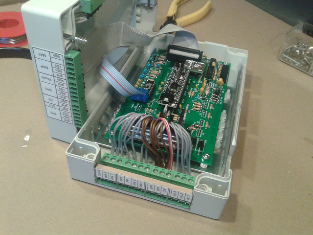
another picture, PCB almost complete:
stay tuned, lots of info and pics to come


 ->
-> 


